The existence of parallel machines and the potential need for parallel applications encouraged us to integrate in the DIVA system the possibility to specify parallel programs. Moreover, the use of graphs is also a suitable way to represent parallelism. Our goal is to integrate new functionalities into the DIVA environment, which allow users to use the parallelism of control and the parallelism of data.
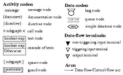
Figure 1. Graphical representation of Script language elements
First, we worked on the visual formalism which can be used to specify a parallel application. It allows to consider data parallelism and control parallelism. This visual formalism will be then complemented by code generators which can detect parallelism and/or translate the directives given in the specification.
We will discuss only the visual formalism in this article. We propose the visual formalism to use, with its semantics, to specify the two forms of parallelism. Some examples will be also presented to illustrate them and to give a comparison with other visual environments for parallel programming.
2. DIVA and data parallelism
Data parallelism is supported by the data-flow. Certain aspects of data-flow, such as diagrammatic representation of data types and data manipulations are described in [7]. We present here other characteristics that are also related to data-flow view.
As data containers, we have three data node types (Figure 1): bag node, queue node and datastore node. They have a specific run-time behavior (store and forward) and must have activity nodes as predecessors and successors. To each data node corresponds the type of data that it contains.
In the data-flow view, arcs represent data flow and connect an output terminal of a node to an input terminal of another node. There are three kinds of data terminals: non-triggering input terminal, triggering input terminal, and output terminal (see Data-flow terminals in Figure 1). Output terminals represent node out-parameters, while input terminals represent node in-parameters. The two kinds of input terminals have a different behavior.
- A triggering terminal is a terminal for which a new data token is required to trigger the execution of the node. Such a terminal may, but doesn't need to, have a default initial value associated with it. If an initial value is defined, it will be used as an initial data token that doesn't need to be produced by another node. Whenever a data token is available on this kind of terminal, it can be used at most once, i.e. the use of the token consumes the token, and a new token is needed, for all triggering terminal, before the node execution can be triggered again. When the execution of the node starts, the token is removed from the terminal and placed in the node's internal space. If a new token arrives on a triggering terminal that already contained a token, the new token replaces the old one. If a new token arrives on a triggering terminal while the node is executing, the token is kept on the terminal until the node is executed again or until a new token replaces it.
- A non-triggering terminal is a terminal the content of which is always available and thus must have a default initial value. It can be seen as a simple data store: the value it contains may be used as many times as needed, and whenever a new token arrives, its value simply replaces the current value.
If the node has one or more triggering terminals, then a new data-flow token is required on each of them for the execution to start. Since non-triggering terminals always have a value available, they are not involved in triggering the execution of the node, unless the node has no control-flow predecessor and has no triggering terminal (i.e. the node has only data-flow predecessors connected to non-triggering terminals).
If a node has only non-triggering terminals, and no control-flow predecessor, its execution can start anytime the graph, in which it is defined, is invoked. After it has been executed once, it will be re-executed anytime one of its inputs changes, i.e. anytime a new token arrives on one of its (non-triggering) input terminals. This mechanism allows one to build reactive systems, i.e. systems for which the outputs are recomputed each time one of the inputs changes.
The execution of a node is triggered based on the arcs that lead to the node and on the terminals to which the arcs are connected. Nodes can be in one of the following states: dormant, waiting for data and active. The transitions from one state to another are governed by rules expressed in Figure 2.
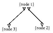
Data parallelism can be detected implicitly when, in the data-flow view, two or more arcs leave a node and point to different destinations (see Figure 3), when these destination nodes have no control-flow predecessors. The execution of these destination nodes can thus be carried out in parallel.
Other cases of data parallelism can be automatically detected based on semantics attached to the data-flow arcs. Generally, there should be a data type match between the origin of an arc and its destination. But one exception is permitted: a new semantic is defined for a data-flow arc connecting (without selection mechanism) an array out-parameter to an in-parameter of the base type of the array. Such an arc would be interpreted differently in a sequential process model than in a parallel process model.
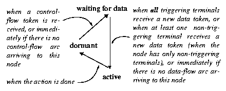
Figure 2. Node state change rules
Figure 3. Data-flow view: node3 and node2 can be executed in parallel
In the sequential process model, this type of connection would imply that the calculation in the destination node is repeated for every element of the array. The base type parameter of the destination node would correspond, at each iteration, to a different element of the array. It could be also the case when the destination data type is an array with smaller dimension than that of the source such that the dimension of the source array is a multiple of that of the destination array. In such a case, the bigger array is used slice by slice, where each slice has the size of the destination array. This last situation can be considered as a generalization of the preceding one.
In the parallel process model, this type of connection would imply that the calculation has to be done in parallel in as many instances of the destination node as possible. It is different from the data parallelism offered in Figure 3. The nodes treated in parallel are not different nodes but multiple run-time instances of the same node somewhat like SIMD (Simple Instruction Multiple Data) parallelism. This situation is called node replication and depends on data types at the two ends of the data-flow arc. In this model, the arc can have a numerical label which would be interpreted as an upper limit to the number of parallel processes simultaneously running.
For instance, if an array of 100 integers is connected to a single integer with an arc labeled with 20, it means that at most 20 instances of the destination node will run in parallel and their calculations will be iterated over as many slices of 20 elements (or less) of the array as necessary to cover the whole array. If the arc is not labeled, it will mean that the run-time system will decide of the optimal number of parallel calculations.
There are still a few aspects to consider:
- assuming that a node has more than one incoming data-flow arc, should there be only one arc along which parallelization can occur?
- shall we assume the output of a node that has been "parallelized" is actually an array of the output type? (e.g. if the output of the parallelized node is of type Y, shall we assume that the actual output will be an array of base type Y?).
To simplify the parallel model, we assume that:
- if there are two (or more) arcs along which parallelization can occur, the corresponding array dimensions must be the same and parallelization will be made on a group of elements which have the same index (see example in Figure 7)
- the outputs of a parallelized node will be buffered, and if the data input of the corresponding successor node is an array, it will be filled in one simple step.
We are still considering alternative behaviors.
3. DIVA and control parallelism
There are two variants of control parallelism in the DIVA system. A node will be able to invoke a subgraph which has its own execution thread and, thus, executes in parallel with the calling script. Such a node is of the 'spawn node' type. It will also be possible to carry out, in parallel, the execution of a certain number of nodes if a condition evaluates to true. The node containing the condition will be the common control-flow predecessor of this group of nodes. This node is of the 'guard node' type. Graphical representations of these two node types are given in Figure 1. These nodes have specific behaviors compared to what is described in Figure 2.
3.1. Spawn node
A spawn node makes explicit the specification of parallel processing. This node is similar to the call node (or 'Subgraph reference' node [8]). It names another script that should be invoked there. But the major difference is that, with the spawn node, the called script is executed in parallel with the calling one, while with the call node the execution of the calling script will resume with the next node when the other script execution has been completed.
The parameters of the invoked script are considered as communication channels between the calling script and the called script, allowing the two parallel processes to exchange data and/or control tokens while both are active. Thus, the spawn node allows a permanent communication between the child process and the main process.
If the spawn node receives a control token from one of its control-flow predecessors, the starting node of the called script receives also a control token. Once the creation of the child process is finished, the spawn node sends a control token to its control-flow successor(s). This allows the main process to continue executing in parallel to the child process.
As for the call node, the syntax of this type of node is rather free. The only convention currently applied is to have the text of the node start with the name of the called script. Figure 12 gives an example of spawn node use.
3.2. Guard node
Nodes of this type contain a boolean expression, the specification of which could be expressed in natural language. The guard node has no close connection with the famous notion of 'guarded command' introduced in [3]. This node allows to launch parallel processing of its successors. It can have several nodes as predecessors and successors. The guard node can have incoming and outgoing data-flow arcs. But it should not transform the data.
Contrary to the other nodes, a guard node in the dormant state becomes active only once all its predecessors have sent a token. But, if the guard node has incoming data-flow arcs, it enters first in a waiting state. It becomes active after all its triggering input terminals receive new data token. As soon as the guard node becomes active, its content (boolean expression) is evaluated. If this evaluation returns true, the node consumes all the incoming tokens (except for the data token on non-triggering input terminals) and sends, in parallel, a control token to all its control-flow successors and data tokens to all its data-flow successors, after which it returns to a dormant state. If the evaluation returns false, the guard node goes to the waiting state until it receives a new data token, making it active again and involving the revaluation of its expression. However, if the guard node has no incoming data-flow arcs and the predicate evaluation returns false, it returns immediately to the dormant state.
In Figure 4, the guard node enters first in a waiting state after node1 and node2 have finished executing. It becomes active once a data token arrives on the triggering terminal from node3, and its expression will be evaluated. If the guard expression evaluates to true, node5, node6 and node7 will start executing in parallel otherwise the guard node goes to the waiting state until it receives a new data token from node 3.
If the guard expression is always true (trivial value), all the guard node successors receive tokens as soon as all predecessor nodes have sent a token. This situation allows to use a guard node like a simple synchronization node.

Figure 4. Guard node with two control-flow predecessors, one triggering input terminal, and one non-triggering input terminal
4. Related work
The use of visual techniques in the domain of parallel computing concerns two distinct areas: visual programming (creation of computer programs) and program visualization (showing the execution process). Our system belongs to visual programming. Some systems already exist in this domain. One can name among others GRADE [9], CODE [10], HeNCE [1], Meander [13] and VPE [12].
The common goal of these systems is to provide an easy-to-use, integrated set of programming tools for parallel application developments. These systems differ by the abstraction level that they offer. For example, VPE is less abstract than CODE and HeNCE. The DIVA system inherits a high level of abstraction from its sequential ancestor model. Another difference is that, for the DIVA system, the node annotations are made in natural language while for these other systems they are made in programming languages such as C or FORTRAN. DIVA thus allows users who are not specialists in computer science to take part in the specification of their applications.
We will show how the various visual programming systems differ through some examples. These examples also illustrate the use of our script language to specify a parallel application. We consider three examples, two of which relate to data parallelism and one of which deals with control parallelism. For each case, we will show how other visual language systems (or environments) specify it. For the clarity of the DIVA scripts, we use the full line to represent the control flow and the dotted line for the data flow. Moreover, the node annotations are entirely displayed there.
4.1. Dot product of two vectors.
Let us suppose that we have two vectors A and B with a dimension of 100, and we would like to calculate the product of these two vectors. Let's also suppose that we have nproc processors available.
The algorithm which is adopted for HeNCE and for VPE is the following:
- each one of the initial vectors A and B is subdivided in nproc subvectors;
- the products of each couple of subvectors are calculated in parallel;
- the sum of these partial results gives the product of the two initial vectors.
Figure 5 shows the corresponding graph and the node annotations with HeNCE [2]. Node init gives the arrays (x and y) their initial values. Each replication of dprod will access a subvector of x and y and perform a dot product on them. Node output sums the results of replicated nodes to form the final result. The designers must enter the annotations of each node. They must also write the code in C language corresponding to the three procedures called in the three nodes.
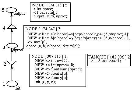
Figure 5. Dot product computation with HeNCE: graph and node annotations
The VPE version [12] is given in Figure 6. Node ReadPrint reads the input vectors and sends subvectors to the N instances of node dprod. It then receives a message containing a partial sum from each dprod node. It adds those partial sums and prints the result. Each dprod node receives a pair of subvectors, performs a partial sum and sends the result back to node ReadPrint. The node annotations contain the message passing primitives (vpe_send, vpe_recv).
With the DIVA environment, the designers simply draw the specification graph (Script) and specify in natural language the processing to be made in each node. The first node is a documentation node and gives the name of the script. The others are directive nodes which contain instructions to the coder. A code skeleton will be generated automatically and then will be completed by others (coders) or by the designers themselves if they are able to do it.
In this example, we find a case of node replication. The replicated node (the second node from the top) calculates the product of an element of A with an element of B. Thus its input parameters are of integer type whereas the output parameter types of its predecessor are array of integer. If nproc >= 100, the multiplications could be made by 100 parallel processes at the same time. But if it is not the case or if a limit value which is lower than 100 has been specified (say n), then the processing would be made a certain number of times (((100 div n) + 1) times) on certain processors ((100 mod n) processors). In the sequential model, the processing would be done 100 times on a single processor.
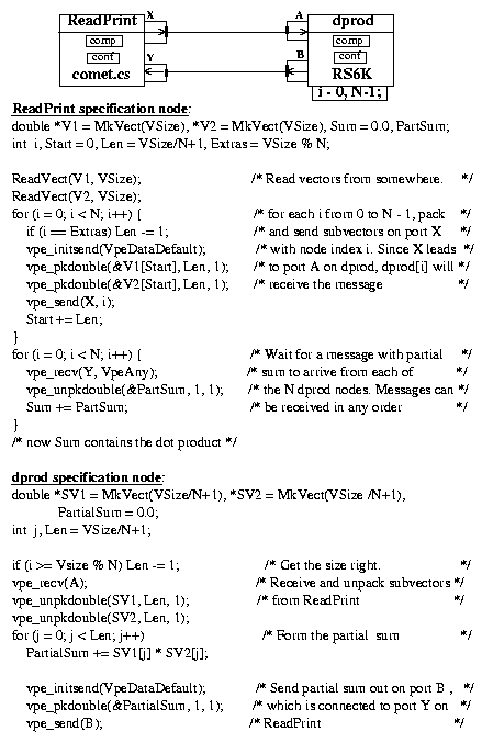
Figure 6. Dot product computation with VPE: graph and comp node specifications
Figure 7 shows us the script (data/control flow) corresponding to this application. On the right we have the parameter lists beside the corresponding nodes. These parameter lists are usually not permanently visible on the visual representation but appear in pop-up panels when the user clicks on the parameter handles (data terminals)
4.2. Sum of the elements of a vector.
Let us suppose that we would like to make the sum of the elements of a large vector (100 elements) by using 10 processors. We will thus subdivide this vector into 10 subvectors and will carry out partial sums in parallel. Afterwards, the partial sums are again added to have the final sum.
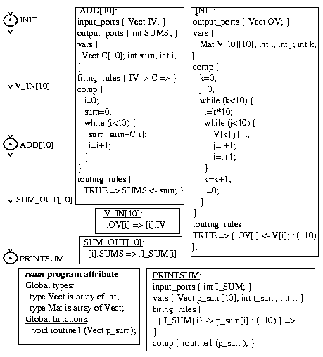
With CODE, we have the Figure 8 graph which is proposed in [11]. The INIT node initializes 10 vectors of 10 elements each. The replicated node (ADD[10]) adds each vector separately, in parallel. The resulting partial sums are then added in the PRINTSUM node to produce the final sum. The user must enter the specification of the three nodes by using CODE's own language and write the procedures called from the nodes.
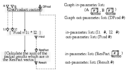
Figure 7. Dot product computation with DIVA: data/control flow and parameter lists
Figure 8. Vector elements sum with CODE: graph, nodes specifications and arcs topologies
With DIVA, we are in the case where the destination in-parameter of the data-flow arc is a subarray of its source out-parameter. The directives which correspond to the nodes are initially written in natural language ( Figure 9).
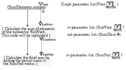
Figure 9. Vector elements sum with DIVA: data/control flow and parameter lists
4.3. Buffer management.
The two preceding examples involve data parallelism which, with the DIVA system, will be detected automatically by the parallel model code generator based on the data types associated to data-flow terminals. Now we will see an example of parallelism of control which needs to be indicated explicitly in the specification graph.
We will specify an application managing a buffer. We will thus have a producer and a consumer which both use (store and forward) the buffer.
A solution with Meander is given in [14. The entire system (see Figure 10) consists of 4 processes: the buffer, the consumer, the producer, and the main process. The main process starts 3 additional processes when executing the create-child (51), sends the intended buffer size to the buffer processes (52 -> 2) and waits in a snd (11) for the report of unused items (53); the wait-child (54) is completed only if all 3 child processes are properly terminated; afterwards the main process terminates itself. Communication is specified graphically by means of the (thick) edges interconnecting snd and rcv, for example (5 -> 42) or (33 -> 6). The user must enter the various annotations of the nodes (see Figure 11 for the buffer process).
With the DIVA system, we will have to create three scripts (one main script and two sub-scripts):
- the main script that calls in parallel the two sub-scripts;
- the producer sub-script;
- and the consumer sub-script.
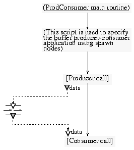
The two sub-scripts, which will be executed in parallel with the main script, are invoked from two spawn nodes (see Figure 12). They have access to the buffer during all their execution. The buffer is modeled with a queue node which is used as data store between the spawn nodes.The main process stops its execution after the two child processes end.
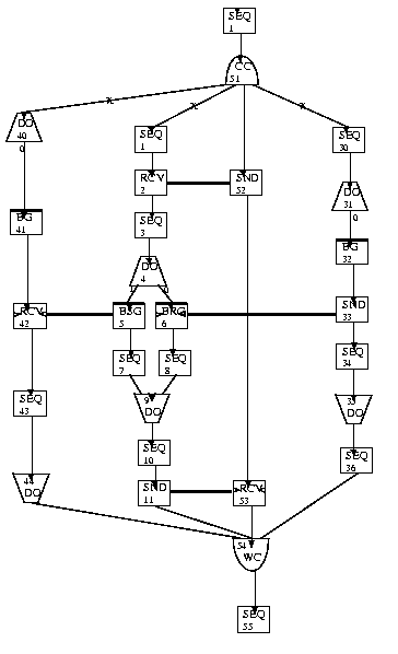
Figure 10. Buffer management with Meander: the four processes
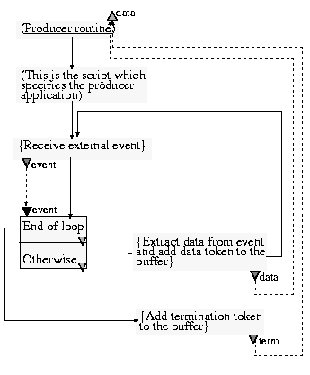
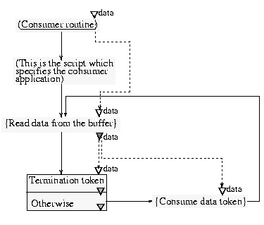
The producer (Figure 13) stops its loop when it receives a special external event. In this case, it puts a termination data token in the buffer. Its execution stops since the node that adds terminatiom token to the buffer has no successor. For the consumer (Figure 14), the loop will be stopped when it finds the termination data token. Let us note that the first test node ('Termination token') does not have any successor when the test is true, which results in the consumer script ending as soon as the test evaluates to true.
5. Conclusion
As we said in the introduction, this extension of the DIVA system to support parallelism affects two levels, the visual formalism and the code generator. This article shows the various research done at the visual formalism level. The visual formalism does not allow the users to specify some issues like data partition, placement. They will be treated by the code generator. The functionalities and the characteristics of the code generator will be described in another article.
We emphasize that the parallel aspects are specified formally by the data and control flow. The specifications in natural language describe the operations to be carried out. A similarity measure is used to find re-use opportunities [4].
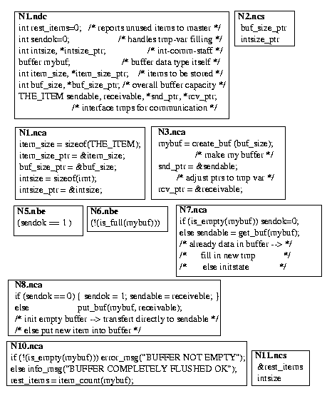
Figure 11. Buffer management with Meander: node annotations for the buffer process.
Figure 12. DIVA main script for buffer management using two spawn nodes
Figure 13. Producer sub-script
Figure 14. Consumer sub-script
References
- A. Beguelin, J. Dongarra, A. Geist, R. Manchek and K. Moore; "HeNCE: A Heterogeneous Network Computing Environment"; Scientific Programming, Vol. 3, No. 1, pp 49-60, August 1993 University of Tennessee Technical Report CS-93-205.
- A. Beguelin, J. Dongarra, A. Geist, R. Manchek, K.
Moore, P. Newton, and V. Sunderam; "HeNCE: A Users' Guide Version
2.0"; June, 1994. Available at
http://www.netlib.org/ncwn/hence-2.0-doc.ps. - E. Dijkstra; "A Discipline of Programming"; ENGLEWOOD CLIFFS, PRENTICE-HALL, 1976.
- Maria del Rosario Girardi; "Classification and Retrieval of Software through their Description in Natural Language"; Ph.D. Thesis No. 2782, Computer Science Department, University of Geneva, Switzerland, 1995.
- Bertrand Ibrahim; "Software Engineering Techniques for CAL"; Education & Computing, Vol 5, pp 215-222, Elsevier Science Publishers, 1989.
- Bertrand Ibrahim; "Courseware CAD"; in proceedings of the IFIP fifth World Conference on Computers in Education, Sydney, Australia, 9-13 July, Anne McDougall and Carolyn Dowling, editors, North-Holland, 1990, pp 383-389, ISBN 0444887504.
- Bertrand Ibrahim; "Diagrammatic representation of data types and data manipulations in a combined data- and control-flow language"; In 1998 IEEE International Symposium on Visual Languages, Halifax, Canada, September 1998, pp. 262-269.
- Bertrand Ibrahim; "Semiformal Visual Languages, Visual Programming at a Higher Level of Abstraction"; In proceedings of the Fifth Conference of the ISAS / The Third Conference of the SCI , Orlando, Florida, USA, July 31-August 4 1999.
- P. Kacsuk, G. Dózsa and T. Fadgyas; "A Graphical Programming Environment for Message Passing Programs"; 2nd International Workshop on Software Engineering for Parallel and Distributed Systems, (PDSE'97), Boston, 1997, pp.210-219.
- P. Newton and J.C. Browne; "The CODE 2.0 Graphical Parallel Programming Language"; Proc. ACM Int. Conf. on Supercomputing, July, 1992.
- P. Newton and S.Y. Khedekar; "CODE 2.0 User and
Reference Manual"; March 24, 1993. Available at
http://www.cs.utexas.edu/users/code/CODE-body.html. - P. Newton and J. Dongarra; "Overview of VPE: A Visual Environment for Message-Passing Parallel Programming"; University of Tennessee Tech. Report CS-94-261, November 1994.
- G. Wirtz; "A Visual Approach for Developing, Understanding and Analyzing Parallel Programs"; In E.P. Glinert, ed., Proc. Int. Symp. on Visual Programming, Bergen, Norway, Aug. 1993.
- G. Wirtz; "Graph-Based Software Construction for Parallel Message-Passing Programs; Information and Software Technology, 36(7):405-412, July 1994.
Site Hosting: Bronco
